
In this Article
- Executive Summary: The Hidden Blueprint
- Essential Esoteric Proportions to Look For
- Tools and Techniques for Geometric Overlay
- Step-by-Step Facade and Grid Analysis
- Case Studies in Civic and Corporate Structures
- Analytical Limitations and Avoiding Pareidolia
Executive Summary: The Hidden Blueprint
Sacred geometry still appears in contemporary civic and corporate architecture, but the serious question is not whether a shape looks suggestive. The serious question is whether the geometry survives measurement.
That distinction matters. A glass facade can seem loaded with hidden rectangles from the sidewalk. A plaza can look ritualized from a satellite image. Then the permit elevation shows routine curtain-wall bays, or the landscape plan reveals a drainage-driven paving layout. The field method has to begin cold: identify repeated geometry, measure it from reliable drawings or corrected site photographs, then separate design evidence from visual coincidence.
For this article, I use “modern” in a narrow way: a civic or corporate structure completed or substantially renovated from early 2015 through late 2024. The useful date is not the press announcement. Use the completion date, occupancy certificate date, or final planning approval date.
Summary: Within established frameworks, start with three first-pass shapes: phi rectangles with a height-to-width ratio near 1.618; vesica piscis forms made from two equal circles whose centers sit on each other’s circumference; and regular polygon grids using 60-degree hexagonal, 72-degree pentagonal, or 45-degree octagonal rotations.
Record the first observation before interpretation hardens around it. Location. Facade viewed. Compass direction. Photograph timestamp. Lens focal length if available. Source type: plan, elevation, aerial image, or street-level image.
That small discipline keeps the investigation from becoming a mood board.
Essential Esoteric Proportions to Look For
The first test is falsifiability. If a proportion cannot be measured, it should not carry the argument.
The Golden Ratio in Bays, Openings, and Voids
Phi is the most abused proportion in architectural speculation because it feels precise even when the measurement is sloppy. The actual check is simple: measure the clear width and clear height of a facade bay, lobby opening, atrium void, or window group. Compare the ratio against phi, about 1.618, then compare it against common construction modules such as 1200 mm, 1500 mm, 2400 mm, or 3000 mm spacing.
If the supposed phi rectangle also fits a standard modular grid with fewer assumptions, the mundane explanation gets priority. The mathematical principles of the Golden Ratio are exacting; field claims should be, too.
The Vesica Piscis in Arches, Logos, and Plazas
Here the question becomes geometric rather than atmospheric. Draw two circles of equal radius. If arch crowns, plaza rings, or logo curves align only when the circle centers are separated by exactly one radius, the form meets the definition. If the circles need stretching, shifting, or selective points, downgrade the claim.
Vesica forms often hide in plain sight because they can be read as soft branding, entrance choreography, or a planning device for intersecting circulation paths. Meaning depends on repetition and documents, not just resemblance.
Platonic Solids as Architectural Language
Platonic references rarely appear as literal solids in office towers. They tend to surface as structural language. Tetrahedral language usually means equilateral triangular framing. Cubic language appears as equal square modules. Dodecahedral or icosahedral claims require repeated pentagonal or triangular networks, not a single five-sided outline on a lobby wall.
Use measured drawings dated within the project design-and-approval window, typically from schematic design through permit issue. Label each source sheet by title, issue date, scale, and revision mark. Revision marks often matter more than renderings; symbolic-looking elements can vanish late, while practical substitutions can introduce new geometry by accident.
Tools and Techniques for Geometric Overlay
What should be in the bag before walking the site?
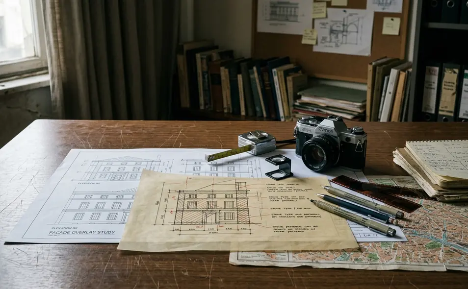
Not much. The physical kit is almost old-fashioned: brass dividers or drafting compass, transparent 180-degree protractor, 300 mm ruler, gridded tracing film, printed satellite or parcel map, and a notebook with page numbers for chain-of-observation tracking.
The digital kit has to do repeatable work. Use CAD or vector-drawing software capable of locked aspect-ratio scaling, angle measurement, layer opacity control, and georeferencing to at least two fixed points. Good fixed points include parcel corners, curb returns, or building grid intersections.
Quick Tip: Shoot the same facade during two windows, approximately 09:00-11:00 and 14:00-16:00 local time. Shadow lines can mimic mullions, relief cuts, and panel joints. Two light conditions expose the impostors.
Blueprint sourcing is less glamorous but more decisive. Search the planning portal by street address, parcel identifier, permit number, architect-of-record field, and project title. Request site plans, elevation sheets, landscape plans, public art submissions, design-review minutes, and zoning-board staff reports.
Set the public-records window wide enough. Search from an estimated 18 months before the first planning submission through around 6 months after the occupancy certificate. Revisions, value-engineering changes, and landscape substitutions often appear after initial design approval.
The same geometry must be checked across sources, not merely spotted in one dramatic image. The plan may show one logic. An elevation may show another. The as-built plaza may show a third.
Step-by-Step Facade and Grid Analysis
Start with control points. Interpretation comes later.
- Establish the baseline. Mark finished floor level, main entry threshold, gridline A or 1 if shown, and the roof parapet. Never use a camera-skewed photograph as the sole baseline.
- Find the structural center. Locate it from structural gridlines, column spacing, lobby axis, or symmetry of the site plan. Document whether the center comes from geometry, circulation, or parcel constraints.
- Trace the primary grid. Mark all repeated mullion, column, paving, and landscape intervals before drawing esoteric overlays. This prevents the overlay from deciding which points deserve attention.
- Map macro-geometry against micro-geometry. Compare aerial plan geometry with street-level elevation geometry. A genuine design system should leave coordinated evidence in site layout, approach axis, facade bays, ceiling coffers, paving, or lighting grids.
- Cross-reference the record. Review design statements, planning minutes, and public-art narratives dated from concept review through final approval. Then compare those documents with built conditions.
Here is the common failure case. A glass tower with repeated rectangles appears to contain phi ratios when viewed from the street. The permit elevation then shows equal-width curtain-wall bays driven by rentable-floor efficiency and panel fabrication limits. The pattern was real. The sacred reading was not.
Note: Do not measure sacred proportions from wide-angle street photographs unless the image has been rectified against known vertical and horizontal edges.
Case Studies in Civic and Corporate Structures
Use anonymized case templates before chasing famous names. Recognition can contaminate the reading.
Financial Headquarters: Hexagonal Grid or Decorative Badge?
Begin with the floorplate and facade module. A single hexagonal logo near the lobby tells little. The stronger test asks whether sixfold or triangular geometry controls column placement, ceiling panels, curtain-wall joints, lobby floor pattern, and exterior plaza paving.
Suppose the lobby ceiling panels form a 60-degree triangular net. The exterior paving repeats the same rotations. The curtain wall aligns every third bay with that interior grid. Now the argument has structure. If the only hexagon sits in the brand mark, the building has a graphic motif, not a building-wide system.
A hexagonal plaza grid can be symbolic, structural, decorative, or merely practical. Its meaning changes depending on whether the same sixfold geometry appears in the floorplate, facade, public-art statement, and approval documents.
Government Plaza: Octagons, Pentagrams, and Public Space
Plazas invite overreading because aerial views flatten practical design into symbols. Map octagonal fountains, eight-path circulation nodes, radial paving, pentagonal planting beds, and diagonal paths. Then verify each feature against the approved landscape plan rather than relying on aerial imagery alone.
Security planning may explain diagonal routes. Accessibility ramps may explain gentle arcs. Parcel setbacks may force clipped corners that resemble octagons. A plaza only begins to support an esoteric interpretation when the geometry persists across circulation, planting, paving, and documented design intent.
Historical Temple, Modern Tower
The comparison should be narrow. Look for axial processional routes, cardinal orientation, proportional rectangles, repeated polygons, and ritual thresholds in documented historical sources dated before the modern building’s design window.
Then ask whether the modern designers cited precedent, symbolism, public art requirements, security planning, sustainability targets, or structural efficiency. Avoid claiming equivalence unless the same geometry governs both plan and elevation. Similar shapes do not create a lineage by themselves.
Analytical Limitations and Avoiding Pareidolia
The conservative classification is the useful one: measured pattern, plausible design intention, documented symbolic intention, or unconfirmed resemblance.
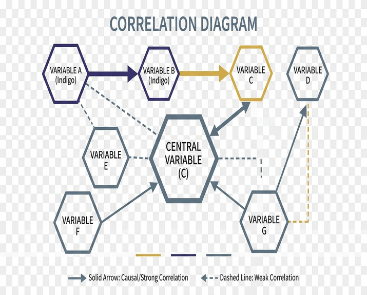
Require at least three independent correlation points before treating a pattern as intentional. For example: matching plan geometry, matching facade module, and a design document or public-art statement that names the concept. A geometric match by itself does not prove occult intent; the claim becomes defensible only when measurements, repeated placement, and documentary context point in the same direction.
Pareidolia is the trap. The eye wants completion. It turns a partial pentagon into a pentagram, a service corridor into an axis, a manufacturer’s panel size into a sacred module.
Redraw the same plan with non-esoteric overlays: standard structural bays, fire-egress paths, sun-shading angles, accessibility ramps, and parcel setbacks. If those explain the geometry with fewer assumptions, downgrade the esoteric reading.
Sacred-geometry analysis is strongest for buildings with accessible drawings, stable public records, and repeated geometry across plan, elevation, and landscape. It is weak for sealed private interiors, heavily altered renovations, and image-only investigations. That caveat is not a retreat. It is what keeps the work from sliding into pattern hunting.
Field Checklist for Spotting Sacred Geometry in Modern Architecture
- Photograph the facade straight-on and record date, time, street position, and viewing direction.
- Collect site plan, elevation sheets, landscape plan, design-review report, and zoning-board materials.
- Mark baseline, center, gridlines, and repeated modules before drawing symbolic overlays.
- Test phi rectangles, vesica piscis circle relationships, and polygon rotations against measured drawings.
- Check whether the same geometry appears in plan, elevation, landscape, and written design context.
- Rule out structural bays, fabrication modules, sun control, access routes, security design, and parcel constraints.
- Classify the result conservatively: measured pattern, plausible intention, documented symbolic intention, or resemblance.